Liquid Cooling Test Bench for Collins Aerospace
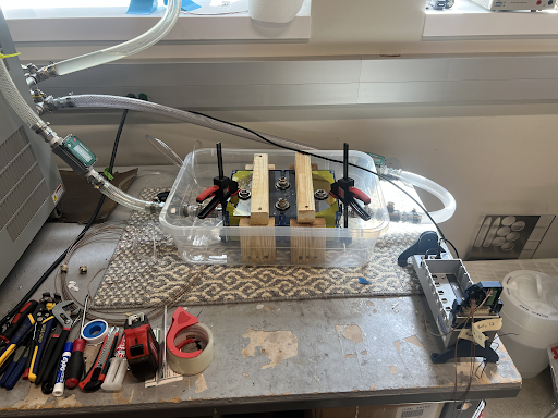
Figure 1. Enclosure where power electronics and thermocouples are mounted in a container with coolant running through it
Key Features:
- Designed and built a test bench for 200W power module and oil-based, coolant to study effects of immersion cooling
- Developing procedures and performing tests between 20 to 150˚C and measuring heat transfer from module to coolant
- Tested bench and recorded data using a design of experiments varying power, setup orientation, and flow velocity
Technologies Used:
- ANSYS IcePak
- LabVIEW
Results:
- A budget-friendly functional flow loop built from easy to source parts
- An initial simulation was developed in ANSYS Icepak which modeled real world findings
- A series of recommendations was provided in a technical report if Collins was to pursue this project further
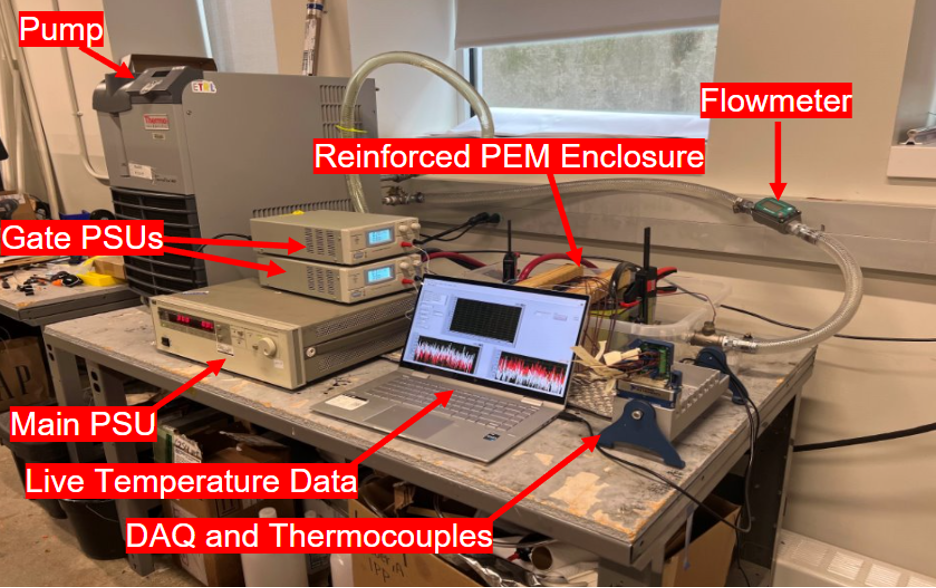
Figure 2. An annotated assembly of all of the components involved
A Power Electronics Module or PEM is used to deliver power to high power consuming to support onboard aircraft systems. Because of the high power draw of a PEM, Collins Aerospace is interested in investigating the feasiblity of cooling a PEM using a liquid. They contracvted out the Unviersity of Illinois for a as part of my 5 students as part of a Senior Design Project to create a minimum viable product to explore this project. The Power Electronics Module used in this project was rated for up to 900W but due to safety concerns and power supply limitations the module was throttled to 200W of heat generation for testing.

Figure 3. A brainstorm of the design
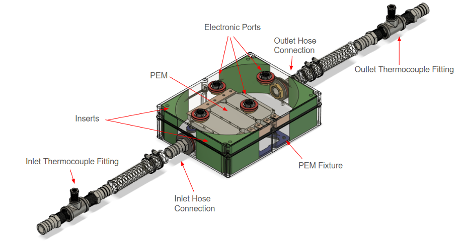
Figure 4. Final CAD Assembly
The enclosure was built from scratch using commercial off the shelf (COTS) parts with sight modifications that can be done in any machine shop. The team was tasked with finding a dielectric coolant with a boiling point of greater than 200˚C to ensure single phase convection.
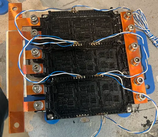
Figure 5. The transistors of the PEM are actually exposed to increase the efficacy of heat transfer during immersion cooling
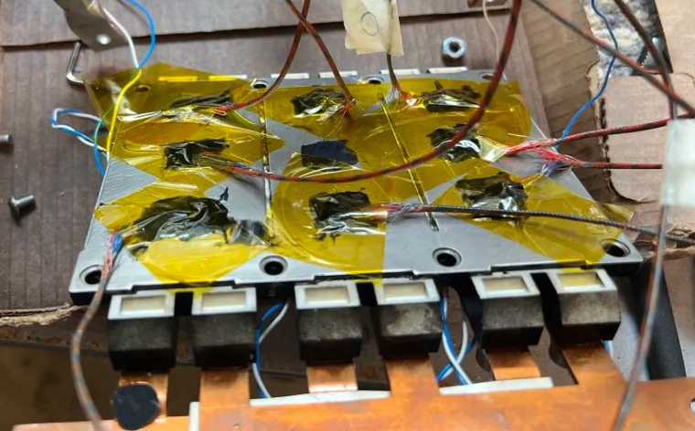
Figure 6. Thermocouples were mounted onto the back of the PEM using Kaptan (electrically resistant) Tape
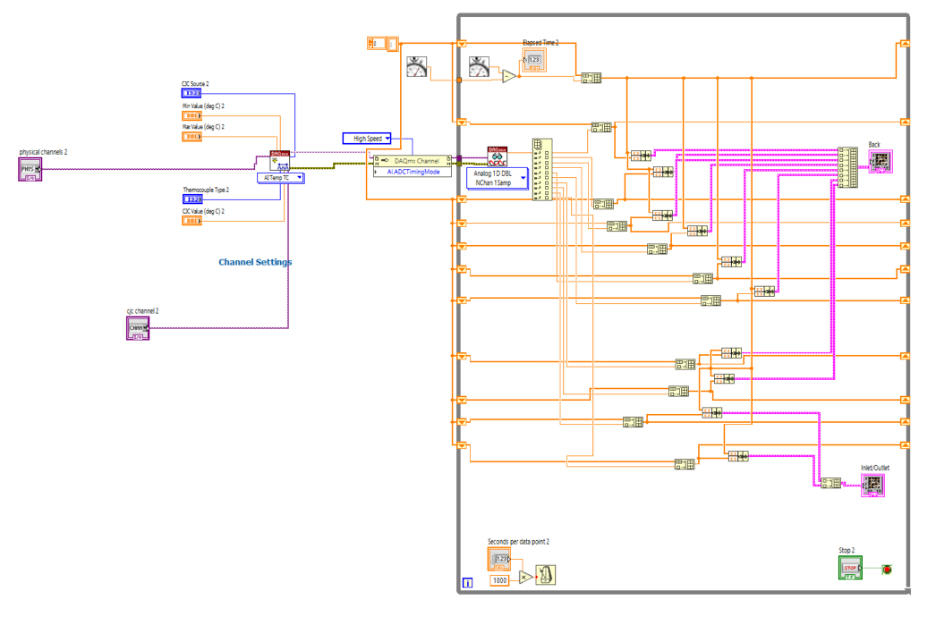 Figure 7. LabVIEW Block Diagram for reading thermocouples
After constructing a test article the team was tasked with conducting experiments to study the following convection conditions
- Single phase convection
- Forced & natural convection
- Steady and transient conditions
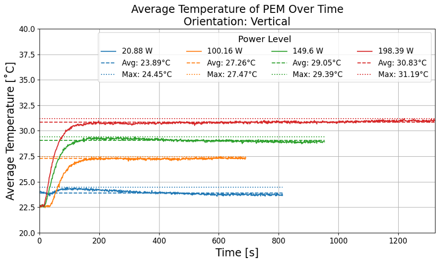
Figure 8. One Temperature vs. Time graphs retrieved from our experiments
The final product was then safely packed and shipped to the Collins Aerospace office in Rockford, IL.
