
Custom 3D Printer gcode for Plastic Sheet Adhesion
Published:
Last updated:

This blog instructs how one can create custom gcode to turn a 3D printer into a finely controlled heated pin for plastic sheet adhesion, this SOP was designed for inflatable pouches for a class, but the adhesion process could have a wide variety of other applications including:
- Adhesion bonding between dissimilar surfaces
- Soft robotics
- Textile bonding
- Art
Workflow Summary
- Create an .svg file
- I’ve been using Figma
- Import into Kiri:Moto
- Export into .gcode file
- Lay out Nylon/TPU layers and tape to bed
- Run gcode file
Process Overview
A high level overview is to design a drawing, I think it’s important to use vector based images because they allow for single lines rather than pixels to denote where to cut. For the image to gcode creation software, I chose Kiri: Moto. Kiri is great because its open source, in the browse, and allows key file I/O compatibility. You can import a svg and export a .gcode file.
The next step is to run the .gcode file in a 3D printer. Thankfully, 3D printer gcode instructions are pretty standardized, and the general commands for controlling the nozzle up and down, as well as the bed and nozzle heating, and coordinate systems are all the same for modern printers.
In the setup I deatil here, a sheet of Nylon on one side and TPU on the other was used. The TPU sides were bonded together.
In this workflow, I set the nozzle and bed temperatures to 260˚C and 50˚C respectively. It’s critical to modify these temperatures, as well as the nozzle depth, according to your own project.
Creating .svg file
I have been creating .svg files using figma since its easy to draw common shapes.
- Create your desired path in Figma, remember the 3D printer will need to trace over the shape edges
- For my workflow I just draw e.g. a square change:
- Enter Dimensions - in Figma, 1 unit = 1mm in the slicer
- The corner radius
- Change the fill color to white
- Turn on stroke outline and change to black. I keep at weight = 1
- I’ve been clicking on the rectangle and exporting as .svg
- I found that if you export the whole page including the background it gets a little finicky later in the process. The issue is that the outside background brings in some artifacts when you import into Kiri:Moto. There is also an issue with merging objects and creating lines rather than creating a singular path in Figma. This has to do with how continuous paths are defined in SVGs and then how Kiri:Moto will interpret individual paths. It is recommended to draw objects that will sufficiently be treated as one path for expected results.
- For my workflow I just draw e.g. a square change:
Importing to Kiri:Moto
Kiri:Moto is like a browser friendly website where you can do CAM work.
- On the left, uncheck Origin Center the axes should move from the middle (with negative X and negative Y coordinates) to the corner so that everything is in positive X and Y coordinates
- Hover over Mode click Drag
Hover over Setup click Machines
Set your workspace to the print volume of the 3D printer
Under gcode macros you will need to copy and paste the following:
For Header:
; --- MK4 Heated Nozzle Welding Header ---
M140 S50          ; set bed temp
M190 S50          ; wait for bed temp
M104 S260         ; set nozzle temp
M109 S260         ; wait for nozzle temp
G21               ; mm units
G90               ; absolute moves
M83               ; extruder relative mode (safe default)
M302 S0           ; allow moves without filament
M86 S0            ; disable crash detection (important for Z contact)
G28               ; home all axes
; move to first XY before lowering Z
; Kiri:Moto will insert the first XY after this
For Footer
; --- MK4 Welding Footer ---
G1 Z10 F600        ; raise nozzle clear
M104 S0            ; turn off nozzle heat
M140 S0            ; turn off bed (if ever used)
M107               ; fan off
M84                ; disable steppers
M30                ; end program
For Knife Down
G1 Z0.25 F600 ; knife down to contact height
For Knife Up
G1 Z10.00 F600 ; raise nozzle safely
Click Save
Hover over file in the top right corner, click Import
- Import your .svg file
- You should now see this:
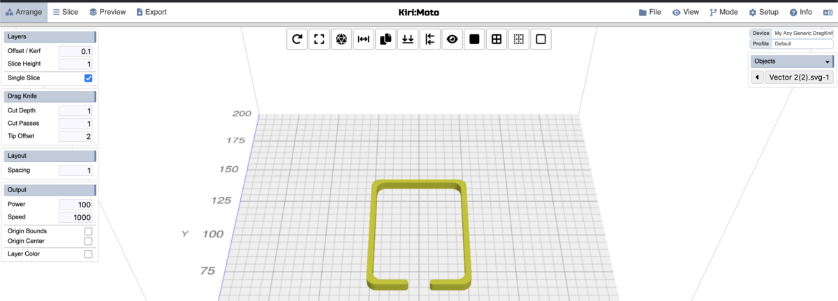
You can try moving the part around in the Arrange step, but I have found that it just reverts to the center of the build plate when I get to the Preview step, if you are able to resolve this issue, please let me know
Click Slice
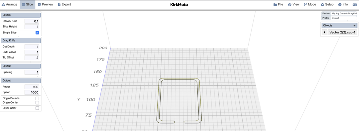
- Click Preview
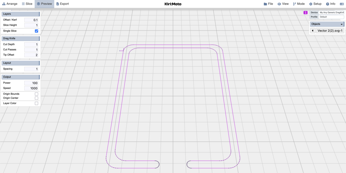
- This is your tool path, if it looks at all incorrect, then you would have to debug a previous step. As you can see in my setup, there’s some kind of artifact in the top left, which I’m not sure why it’s there (I think that’s the start/end of the path?). It’s possible it won’t show up when actually doing the printing process.
Click on the top left Export
- Export as .gcode


Printing on Prusa MK4
When printing on a Prusa I uploaded the .gcode and it gave a warning about input shaping. This likely is just whining about this topic which obviously isn’t implemented in our custom gcode generation. I just clicked the override option and it printed fine